Why Great Aunt Alma should take up tai chi
The short answer: because of its physical benefits. Activities like yoga and tai chi can lead to improvements in balance abilities and overall physical performance.
Let's say that Great Aunt Alma is a typical healthy senior citizen. She likes to go for long walks, she's never broken a bone, and she doesn't have any specific disorders or diseases. But she tends to move more slowly and cautiously than younger adults. And if a distracted little kid bumped into her, she would be more likely to fall than a younger adult would. Doctors and scientists have conducted a plethora of research that can quantify these age-related changes in many different ways.
If you ask someone to stand quietly in place for a period of time, they will sway a little bit, slowly and continuously. (This is because of how the brain controls posture.) Elderly adults tend to have greater sway than young adults. Also, if you ask someone to lean and reach as far as they can in any given direction, they will reach as far as they can without falling; elderly adults tend to reach less far than younger adults, and they also reach to a smaller percentage of their actual capacity. In other simple tests of mobility such as the sit-to-stand test (stand up from a chair) and gait initiation tests (from a stand-still, begin walking), there is more evidence to show that elderly adults move more slowly and cautiously; these changes have been quantified using various measures of body displacement, velocity, acceleration, and timing.
But who says Great Aunt Alma is doomed to be ever more feeble and wobbly? Several studies -- and two in particular which I read recently -- have demonstrated improvements in elderly adults' balance abilities after practicing activities such as tai chi, yoga, and so-called "soft gymnastics" for some period of time. For example,
a study by Vallabhajosula et al. tested six older adults who didn't perform any kind of regular physical activity and who had some degree of "mobility disability." For 16 weeks, they practiced tai chi for one hour, three times each week; as a simple measure of their mobility and balance, they performed gait initiation testing at the start and again at the end of the 16 weeks. After 16 weeks of tai chi, these people were moving faster and more strongly than they had before. Now, Great Aunt Alma is more likely to stay on her feet when that distracted little kid bumps into her.
My father has sworn by the benefits of yoga ever since I can remember. I know that when I do yoga regularly, my chronic back tension and muscle aches are greatly reduced. Other research studies have shown that regular practice of tai chi or yoga can improve balance and gait in elderly adults, can improve balance and motor control in people with Parkinson's disease, and can lead to reduced pain from arthritis and fibromyalgia. There are plenty of explanations for why and how, but the main point here is that it's really good for your physical health.
Further non-technical reading:
Washington Post:
"Yoga for seniors can help with balance, agility and strength."
Harvard Health Blog:
"Try tai chi to improve balance, avoid falls."
Johns Hopkins Arthritis Center:
"Yoga for Arthritis."
New York Times:
"Tai chi reported to ease fibromyalgia."
New York Times:
"Tai chi benefits patients with Parkinson's."
--
Labels: engineering, my future, science
Try again. Fail again. Fail better.
Martin A. Schwartz wrote a thought-provoking essay on how scientific research makes us feel "stupid" and why that's perfectly OK. He shares an anecdote from his days as a PhD student, in which he came across a question that no one could give him the answer to. "That's when it hit me," he writes. "That's why it was a research problem. And being
my research problem, it was up to me to solve... The crucial lesson was that the scope of things I didn't know wasn't merely vast; it was, for all practical purposes, infinite. That realization, instead of being discouraging, was liberating. If our ignorance is infinite, the only possible course of action is to muddle through as best we can."
That is a foundational idea in scientific research. As Schwartz puts it, "Science involves confronting our 'absolute stupidity'. That kind of stupidity is an existential fact, inherent in our efforts to push our way into the unknown." The scientific process (ask a question, form a hypothesis, test your hypothesis, and draw conclusions) is being "stupid" in a productive way. "Productive stupidity means being ignorant by choice. Focusing on important questions puts us in the awkward position of being ignorant. One of the beautiful things about science is that it allows us to bumble along, getting it wrong time after time, and feel perfectly fine as long as we learn something each time... The more comfortable we become with being stupid, the deeper we will wade into the unknown and the more likely we are to make big discoveries."
In summary: going through the scientific process = productive stupidity. Or, as in the titular quote of this post, "Try again. Fail again. Fail better." That wonderful gem is from Irish writer and Nobel prizewinner Samuel Beckett, who clearly understood that we learn best by trial and error; whether or not we ever reach our original goal is relatively unimportant, as long as we clear up some of our stupidity along the way.
Read Schwartz's full essay: "The importance of stupidity in scientific research"--
Labels: engineering, philosophy, ponderings, science
Osteoporotic candy bars

Human trabecular bone is the spongy-looking type of bone found inside the dense outer layers of cortical bone. (For a more complete explanation,
go here.)
Osteoporosis is a condition in which bone loses some of its density; this change is especially prominent in the trabecular bone. I read about a study by some Welsh medical professionals in which they compared Crunchie (top right) and Aero (bottom right) candy bars to normal and osteoporotic human trabecular bone, respectively.
No, really.
At first I was a little surprised that it was actually published, let alone that these people actually conducted and wrote up this study. When I took the time to actually read the paper, however, I came to admire the practicality.
The basic idea here is that when medical professionals discuss bone health with patients, particularly when explaining the risks involved with osteoporosis (most notable of which is increased fracture risk), it helps to have a visual aid. Apparently the authors of this study noticed that Crunchie and Aero bars were a popular teaching tool, and so they decided to test the validity of this comparison.
I won't go into the technical details here, but their test methods were surprisingly thorough. What they found, in the end, is that the mechanical properties of the candy bars don't really compare all that well to actual bone. However, for the purposes of providing a simple visual aid for describing bone structure, these candy bars are fine examples.
Read: P. Jones, S. Jones, D. Stone:
Accuracy of comparing bone quality to chocolate bars for patient information purposes: observational study. British Medical Journal 2007, 335:1285-1287.
--
Labels: engineering, food, science
The technological singularity: future or fantasy?
Over the weekend, I read
this fascinating series of articles in the June 2008 issue of
IEEE Spectrum, addressing the concept of the "technological singularity" which some say will happen by the year 2030.
Spectrum executive editor Glenn Zorpette describes it thus:
"The singularity is supposed to begin shortly after engineers build the first computer with greater-than-human intelligence. That achievement will trigger a series of cycles in which superintelligent machines beget even smarter machine progeny, going from generation to generation in weeks or days rather than decades or years. The availability of all that cheap, mass-produced brilliance will spark explosive economic growth, an unending, hypersonic, technoindustrial rampage that by comparison will make the Industrial Revolution look like a bingo game." (
Full article >>)
Some believe that this singularity will lead, in short order, to a kind of technological rapture. One of the skeptics, science journalist John Horgan, describes this view flippantly, but not inaccurately:
"Like paradise, technological singularity comes in many versions, but most involve bionic brain boosting. At first, we'll become cyborgs, as stupendously powerful brain chips soup up our perception, memory, and intelligence and maybe even eliminate the need for annoying TV remotes. Eventually, we will abandon our flesh-and-blood selves entirely and upload our digitized psyches into computers. We will then dwell happily forever in cyberspace where, to paraphrase Woody Allen, we'll never need to look for a parking space... Notably, singularity enthusiasts tend to be computer specialists, such as the author and retired computer scientist Vernor Vinge... and the entrepreneur Ray Kurzweil. Intoxicated by the explosive progress of information technologies captured by
Moore's Law, such singularitarians foresee a 'merger of biological and nonbiological intelligence,' as Kurzweil puts it, that will culminate in 'immortal software-based humans.' It will happen not within a millennium, or a century, but no later than 2030, according to Vinge... Kurzweil says he has adopted an antiaging regimen so that he'll 'live long enough to live forever.'" (
Full article >>)
Researcher John Casti, however, foresees the singularity going in the opposite direction:
"I think it's scientifically and philosophically on sound footing. The only real issue for me is the time frame over which the singularity will unfold. [The singularity represents] the end of the supremacy of
Homo sapiens as the dominant species on planet Earth. At that point a new species appears, and humans and machines will go their separate ways, not merge one with the other. I do not believe this necessarily implies a malevolent machine takeover; rather, machines will become increasingly uninterested in human affairs just as we are uninterested in the affairs of ants or bees. But it's more likely than not in my view that the two species will comfortably and more or less peacefully coexist -- unless human interests start to interfere with those of the machines." (
Full article >>)
Here, then, is a view of a different kind of singularity (which is, in my opinion, a more plausible one), as proposed by MIT robotics professor Rodney Brooks:
"My own view is that things will unfold very differently... an artificial intelligence could evolve in a much different way. In particular, I don't think there is going to be one single sudden technological 'big bang' that springs [a human-level artificial intelligence, or AI] into 'life.' Starting with the mildly intelligent systems we have today, machines will become gradually more intelligent, generation by generation. The singularity will be a period, not an event.
"This period will encompass a time when we will invent, perfect, and deploy, in fits and starts, ever more capable systems, driven not by the imperative of the singularity itself but by the usual economic and sociological forces. Eventually, we will create truly artificial intelligences, with cognition and consciousness recognizably similar to our own. I have no idea how, exactly, this creation will come about. I also don't know when it will happen, although I strongly suspect it won't happen before 2030, the year that some singularitarians predict.
"But I expect the [AIs] of the future -- embodied, for example, as robots that will roam our homes and workplaces -- to emerge gradually and symbiotically with our society. At the same time, we humans will transform ourselves. We will incorporate a wide range of advanced sensory devices and prosthetics to enhance our bodies. As our machines become more like us, we will become more like them." (
Full article >>)
The questions are many; the speculation runs rampant. Will machines ever be as smart as humans? Will they ever achieve "consciousness"? Will they be our helpers, our caretakers, our overseers? Eventually, time will tell -- assuming that the human race doesn't first undergo some kind of cataclysmic event (e.g., an
Andromeda strain, a nuclear holocaust, extraterrestrial enslavement, the Biblical end of days, etc.).
--
Labels: engineering, my future, philosophy, ponderings, science
Modeling the cardiovascular system
There are several popular models of the cardiovascular (CV) system. Depending on your training and experience, one may make more sense than others. Personally, I prefer the fluid flow model; incidentally, this is probably the closest analog to the actual CV system itself, because blood behaves largely as a fluid.
The Windkessel fluid flow model is relatively straight-forward, with elements representing the aorta and the peripheral circulation (i.e., all of the other veins, arteries, etc. in the body). The aorta is modeled by an elastic chamber, exerting pressure on the fluid it contains, and the peripheral circulation is modeled as a rigid tube of constant resistance; the system input is given as a volume inflow rate.
Another analog to this model is that of an electrical circuit:
Fluid element ~ Circuit element
Flow rate ~ Current
Pressure ~ Voltage
Elasticity ~ Capacitance
Fluid inertia ~ Inductance
Valves ~ Diodes
Resistance ~ Resistance
The circuit can be laid out as follows:
The heart will be represented by an alternating-current (AC) current source, providing a current (blood flow rate) of specified period and amplitude (ranging from zero to a positive value). The flow will then pass through a diode (valve) to prevent backflow into the source (heart). Here, current (blood flow) can pass through the diode (valve) in one direction only.
The flow then encounters an inductor (arterial element) and resistor (aorta) in parallel. Here, the resistance is the proportionality of the voltage (pressure) across the element to the current (blood flow rate) through it; the inductor (inertial component) induces a voltage (pressure) that opposes any change in current (blood flow rate).
Following this, the flow encounters a capacitor (systemic/arterial compliance) and resistor (systemic resistance) in parallel. Here, the capacitor (compliance/elasticity) stores an amount of charge (blood volume) proportional to the voltage (pressure) across the element (aorta); i.e., it stores an amount of energy proportional to one-half the square of the voltage (pressure). Resistance here is the same as described above.
The circuit after this point goes back to the source, with a branch to common ground (blood supply, "reservoir"). Here, ground (supply) merely provides a reference "low" voltage (pressure) for the rest of the circuit.
>> Cole et al. (2005):
"A LabVIEW Model Incorporating an Open-Loop Arterial Impedance and a Closed-Loop Circulatory System," Annals of Biomedical Engineering.
--
Labels: engineering, science
OK, I think my brain just exploded
This particular recurrence of Exploded Brain Syndrome may have been caused by the
sheer awesomeness of this photograph and the accompanying news articles.

Just, uh, wow. I cannot summon the words to describe just how
incredibly awesome this is. It's like my childhood dreams about flying.
Read:
>>
"Rocketman flies over Alps with jet-pack strapped to his back">>
"Holy Jetpacks, Fusion Man! Swiss Man Flies With Own Wings"--
Labels: engineering, imagine yourself here, travel
It's Alive!
Robotics is a field in which I don't have a lot of experience, but I find the results terribly cool. Especially fascinating are those robots which are designed for biofidelic movement, or which mimic the movement capabilities of living creatures. Here is a perfect example: Boston Dynamics' DARPA-funded "BigDog."
Mobile Robots Take Baby Steps (full article >>)"
A robot dog could one day become a soldier's best friend -- if an Army program works out as planned."
New Video: Robot Mule Conquers Ice, Snow (full article & video >>)"
BigDog, the alarming life-like, four-legged robot, is back in action. And this time, it's trudging through snow, marching up hills, and picking itself up after slipping on some ice."
--
Labels: engineering, science
Injury repair in the central nervous system
This is such a promising development. Also, you know, it's really cool science.

Injuries to the central nervous system (CNS) are notoriously difficult to repair, though in many cases the surrounding CNS tissues adapt to work around the resulting scar. This "glial scar" is very inhibitory to the regeneration of damaged axons, which carry outgoing signals from neurons (signal-conducting nerve cells). In order to understand the inhibitory nature of the glial scar and consequent failure of axon regeneration after CNS injury, we should first understand the cells and processes involved in the formation of the glial scar.
When CNS tissue is damaged it undergoes an injury response called reactive gliosis, or glial scarring. This consists of a series of cellular and molecular events that occur and change over a period of several days; the glial scar structure evolves over time as various cells arrive and participate at different times. The main cell types involved are the neurons themselves, as well as the surrounding glial tissue, which consists of astrocytes (general support cells, providing structural stability and helping to regulate the extracellular environment), microglia (immune cells, the "garbagemen" of the CNS), and oligodendrocytes (provide insulation for axons in the form of myelin sheaths).
Immediately following injury, myelin debris (from damaged oligodendrocytes) will be released into the neural environment as oligodendrocytes and other cells in the injured area are damaged and die. In the first few days following injury, the primary entering cells are microglia. The lesion (damaged area) also expands during this time. The mature glial scar consists mainly of a tightly-woven network of astrocyte processes.
Astrocytes around the lesion exhibit abnormal growth and some undergo cell division; the end result of this activity is the dense, predominantly astrocytic composition of the glial scar. It has been found that this tissue can be both inhibitory to and supportive of axonal regeneration, depending on changes in the CNS environment and/or the population of glial scars by an as-yet undetermined sub-type of astrocyte which is inhibitory.
Oligodendrocytes are directly damaged by traumatic injury to the CNS, causing the release of myelin debris and some oligodendrocyte death. Glial scars, therefore, usually contain some oligodendrocytes and myelin debris. It has been shown that mature oligodendrocytes and myelinated areas of the CNS are inhibitory to axon growth. Also, it has been seen that oligodendrocyte precursor cells are recruited en masse to CNS lesion sites; these cells express several proteoglycans (dense molecular complexes of proteins and polysaccharides) that are inhibitory to axon regeneration.
Microglia exhibit activation and division following injury, and migrate to the injury site, becoming more macrophage-like over time ("macrophage" essentially means "great eater," so you can guess what a macrophage does). Collective evidence suggests that microglia may actually support regeneration, as long as nothing happens to make them overtly toxic.
Interestingly, it has been shown that the eradication of all CNS glia from the lesioned area results in an environment in which robust axonal regeneration can occur for a period of about 4 days, until glia re-invade the area.

With this in mind, we turn to the potential use of a self-assembling nanofiber peptide scaffold. This novel scaffold is a hydrogel (content is over 99 percent water, with 1 to 10 milligrams of peptides per milliliter of water) that forms when a self-assembling peptide (SAP) solution is exposed to salt solution similar to that found in the human body. The figure at right (click to enlarge) shows (a) a molecular model of the SAP, (b) a microscopic image of the SAP nanofibers, (c) a microscopic image of the scaffold, and (d) a photograph of the hydrogel. The components of the scaffold are amphiphilic oligopeptides that have repeated alternating ionic hydrophilic & hydrophobic amino acids. These form beta-pleated sheets with distinct polar & non-polar surfaces. Structurally, macroscopic scaffolds have been formed in various shapes and sizes, depending on SAP concentration, total amount of SAP solution, salt concentration, and the geometry of the processing apparatus. These structures consist of individual interwoven fibers of about 10 to 20 nanometers (one-trillionth of a meter) in diameter, with the density of fibers correlating with the concentration of the SAP solution.
Here's the "really cool science" part. In one study, Holmes et al. seeded neural cells on SAP scaffolds. These cells underwent extensive outgrowth along the contours of the scaffolds; further evidence suggested that the scaffolds also supported the formation of functional neuron synapses.

In another study conducted by Ellis-Behnke et al., a tissue gap was created in the hamster midbrain (by deep transection of the optic tract). When treated with SAP solution, this gap was seen to be reduced or completely eliminated by 72 hours post-surgery and in all subsequent examinations, as compared to the saline-treated controls, which remained visible in macroscopic examination at all times post-surgery. The figure at right shows typical examples from 30 days post-surgery of (a) the saline control case and (b) the SAP-treated case. The SAP-treated animals showed axon regeneration through the injury site; the control animals showed no axon regeneration. Here the SAP treatment was generally found to support axon regeneration with a correlating return of functional vision.
Both of the above studies included tests of the body's toleration of the SAP solution; after an injection of the SAP solution into muscle tissue, examinations found no detectable toxic effects and no observable signs of structural abnormalities, muscle necrosis, inflammation, or motor impairment. Where the SAP solution was injected into brain tissue, no apparent inflammatory response was found; in addition, it was discovered that the amino acid degradation products of the scaffold are mostly eliminated from the body within 3-4 weeks post-injection.
Also, one important feature of the SAP scaffold is its ability to fill irregular voids (because it is a hydrogel) such as injury sites in damaged tissue. This allows close contact between the scaffold nanofibers and surrounding tissues.
References:
> J.W. Fawcett et al.:
"The glial scar and central nervous system repair" [PDF, 183 KB],
Brain Research Bulletin, 1999.
> T.C. Holmes et al.:
"Extensive neurite outgrowth and active synapse formation on self-assembling peptide scaffolds" [PDF, 522 KB],
Proceedings of the National Academy of Sciences, 2000.
> R.G. Ellis-Behnke et al.:
"Nano neuro knitting: Peptide nanofiber scaffold for brain repair and axon regeneration with functional return of vision" [PDF, 1.7 MB],
Proceedings of the National Academy of Sciences, 2003.
--
Labels: engineering, science
"Whiplash" injuries: a car safety lecture
Today we're going to learn about one of our friendly vehicle safety features, the "head restraint" (apparently, it is not properly referred to as a "head rest"), how it can save us from nasty "whiplash"-type neck injuries, and how to properly adjust it so that it will be more effective in the event of a crash.

In a rear-impact car crash, as the vehicle is effectively given a shove forward, a poorly protected occupant will undergo three primary phases of movement, as illustrated in the three-part diagram above [IIHS, 1997]. Initially, the torso is forced against the seatback and is pushed forward; the head, prior to contacting the head restraint, initially remains level and lags behind the torso. This results in a characteristic "S"-shape of the neck, where the upper portion of the neck is in flexion while the lower part is in extension (above, left). Following the "S-phase" is the extension phase, in which poor head support will allow the neck to transition into full extension (above, center). Here the torso may "ramp" up the seatback, causing the head restraint to provide even less head support. The forces on the head then accelerate it to catch up with and pass the torso, giving rise to the full flexion or "rebound" phase (above, right). So-called "whiplash" injuries may occur in one or more of these phases. In general, it is thought that the risk of whiplash injuries may be reduced or even completely eliminated if we can minimize relative motion between the head and torso. Controlling this relative motion involves various safety features, but head restraint geometry is especially important to reducing the risk of whiplash injuries in rear-impact crashes.

The two common measurements of head restraint geometry are vertical offset and horizontal backset. Vertical offset is commonly measured as the distance of the head’s center of gravity above the top of the head restraint; in U.S. federal safety regulations, this measurement is replaced by that of height above the so-called "seating reference point" (SRP). Horizontal backset is measured as the horizontal distance between the back of the head and the head restraint. The Insurance Institute for Highway Safety (IIHS) and the Research Council for Automobile Repair (RCAR) commonly define these as shown in the diagrams above [RCAR, 2001]. Studies over the last four decades have generally agreed that whiplash will be reduced if the head restraint is positioned sufficiently high and close behind the head. Independently from federal regulation, IIHS evaluates head restraints according to guidelines set by RCAR. IIHS recommended that head restraints have a vertical offset of less than 90 mm (3.5 inches), so as to make the top of the head restraint at least level with the head’s center of gravity, and a backset of less than 100 mm (4 inches) [IIHS, 1997].
As of January 1, 1969, Federal Motor Vehicle Safety Standard (FMVSS) No. 202 required that all passenger cars manufactured for U.S. sale must have a head restraint in the front outboard seating positions that could achieve a specified height above the SRP, providing adequate protection for a 50th-percentile male [Kahane, 1982]. This standard has not changed since then. According to IIHS, the standard is weak; two major deficiencies are the lack of a minimum height requirement for head restraints in the down position, and the lack of a backset requirement. FMVSS 202 states only that head restraints must achieve a certain minimum height above the SRP when in the fully-extended position; when adjustable head restraints meeting this requirement are left in the down position, the occupant will be inadequately protected. In addition, the required height is only minimally protective. An IIHS evaluation of 1997 model year cars rated over 50% as having poor head restraint geometry, and less than 3% were rated "good" [IIHS, 1997].
To address the deficiencies, the National Highway Traffic Safety Administration (NHTSA) has revised FMVSS 202 in recent years [NHTSA, 2000]. Effective Sept. 1, 2009, head restraints must achieve a new, greater height above the SRP and lock in this position, with a specified minimum lowest height; the head restraint's backset must also fall within a specified range in any adjustment position. According to NHTSA, the new front outboard standards will provide adequate protection for 99.7% of the male population and all females, where "adequate protection" is defined as the head restraint reaching at least as high as the head’s center of gravity.
IIHS and RCAR support these revisions, but nonetheless there is still concern that the revised standards are not what they should be [IIHS, 2001]. RCAR recommended, and IIHS has adopted, stricter testing standards consisting of both geometric and dynamic tests [RCAR, 2006]. By these standards, an IIHS evaluation of 2004 model year cars rated 80% as having "good" or "acceptable" head restraint geometry; however, once seats passing this static geometry test were subjected to RCAR dynamic tests, ratings dropped significantly. By the combined static and dynamic testing standards, only about 33% (24 out of 73) passed with a rating of "good" or "acceptable." Including the 24 car seats that did not pass the static test, a total of about 56% (54 out of 97) were rated "poor" [IIHS, 2004].
With the average level of current technology, it's important to promote education among vehicle drivers and occupants alike. Most occupants don't properly position their adjustable head restraints; in many cases this may be due to mere ignorance and/or indifference, but it is likely that many other people leave their head restraints down for reasons of comfort. Ford Motor Company, for example, reported a recent increase in customer complaints pertaining to head restraint comfort; it is believed that these complaints correlate with reduced backsets in head restraints [NHTSA, 2004].
Next time you hop in the car, check your head restraint. The first time I did so, I was dismayed to realize that mine was positioned far too low to provide any real protection against rear-impact whiplash injuries. Now, however, it's adjusted as it should be. Remember: horizontal backset within 4 inches, and vertical offset within 3.5 inches, or such that the top of the head restraint is at least level with your head’s center of gravity. If you fail to comply with these recommendations, I will feel free to call you stupid.
References and further reading:
>> IIHS (1997):
"Special Issue: Head Restraints" [PDF, 575 KB],
Status Report Vol.32, No.4.
>> RCAR (2001):
"A Procedure for Evaluating Motor Vehicle Head Restraints" [PDF, 471 KB].
>> C.J. Kahane, NHTSA (1982):
"An Evaluation of Head Restraints.">> NHTSA (2000):
FMVSS 202: Head Restraints, Code of Federal Regulations, Title 49, Part 571.202.
>> NHTSA (2004):
"Final Regulatory Impact Analysis, FMVSS No. 202 Head Restraints for Passenger Vehicles" [PDF, 4.3 MB].
>> IIHS (2001):
"New head restraint rule would prevent many whiplash injuries, but proposed dynamic tests could compromise safety" [PDF, 230 KB],
Status Report Vol.36, No.4.
>> RCAR (2006):
"RCAR-IIWPG Seat/Head Restraint Evaluation Protocol" [PDF, 3.2 MB].
>> IIHS (2004):
"Special issue: protection against neck injury in rear crashes" [PDF, 504 KB],
Status Report Vol.39, No.10.
--
Labels: engineering, everyday, travel
"Gender-sensitive" knee implant designs
Apparently this is the next big thing in TKA (total knee arthroplasty). Back in 2006, both Stryker and Zimmer were touting their latest TKA designs; each claimed to be the first with a design created specifically with the female anatomy in mind.
The resulting debate in business and medical forums provided me with both amusement and annoyance. (Apparently I wasn't the only one rolling my eyes over the whole argument; back in March 2006, when the advertising campaigns for Zimmer's
Gender Solutions High-Flex Knee and Stryker's
Triathlon Knee System were running in high gear -- both designs were highlighted at the annual meeting of the American Academy of Orthopedic Surgeons -- Colin Barr of TheStreet.com included the marketing tug-of-war in his column,
"The Five Dumbest Things on Wall Street This Week.")
The idea of a gender-specific knee is an important step forward in the slowly evolving area of TKA. There are many well-documented differences between the male and female knee, including fat distribution, anatomical alignment, and bone structure; for example, the female femur and tibia are narrower and more elliptical in the sagittal plane. This idea makes a lot of sense to me.
There are skeptics. DePuy and Biomet, for example, have gone on record with the opinion that the anatomical differences between the male and female knee are not sufficient to warrant a gender-specific TKA design. However, I'm still working on digging up any out-and-out refutations of the pro-gender-specific arguments, of which there seem to be no particular shortage.
Further reading:
"The Female Knee: Anatomic Variations" (S. Conley et al.),
J. Am. Acad. Orthop. Surg., 2007.
"Total Knee Replacement for Women" [PDF, 3.6 MB] (J.N. Argenson),
European Musculoskeletal Review, 2006.
"Gender Specific Knee Replacement Implants" (J. Cluett),
About.com Orthopedics, 2007.
"Knee Replacements, Designed for Women" (A. Aubrey),
National Public Radio, 2007.
--
Labels: engineering, science
Car accident injuries

Before your next car accident, let's consider some of the myriad factors that affect how things may or may not go horribly wrong.
Occupants:- Front
>> Outboard only: driver and passenger- Rear
>> Outboard (2) and centerImpact/collision types:- Front
- Rear
- Side
- Oblique (bi-axial)
- Rollover
Vehicle safety features:- Seatbelts
>> Lap and shoulder belts
>> Belt auto-catch mechanism- Head restraint (headrest)
>> Height and distance away from head- Seat
>> Frame stiffness (resistance to bending and/or failure)
>> Seat stiffness (cushioning; resistance to loading by the occupant's torso)
>> Contouring (when the seat is loaded by the torso, how will the shape and relative stiffness of different sections of the seat affect the forces that build up on the torso?)- Airbags
>> Front, side, etc.Other factors:- Safety feature performance
- Internal structural failure
>> Displacement of vehicle components (e.g., if the door panel fails, you might end up with a piece of sheet metal in your ribcage)- External structural failure
>> Penetration of extravehicular objects into interior space (e.g. tree branches, signposts, meteors)- Occupant orientation at moment of impact
>> Is the torso twisted? Are the legs crossed? Etc.- Occupant's voluntary reactions to impact
>> E.g. bracingSome possible injuries and causes:- Steering column impact injuries
>> Usually seen only in frontal impacts; unique to driver position- Upper extremity injuries
>> Usually due to occupant bracing- Lower extremity injuries
>> Especially prevalent in frontal impacts; usually due to compressive loading- Whiplash-related injuries (neck)
- Head injuries
>> Especially prevalent in side impacts; can occur in frontal impacts due to poor shoulder belt performance- Torso injuries (thoracic, abdominal, pelvic)
>> Especially dependent on belt and seat performance- Injuries due to excessive loading of shoulder and/or lap belts
Now, doesn't that just make you want to go out and get into a high-speed rollover crash?
--
Labels: engineering, imagine yourself here, travel
Round-up of the pet project
Here's my summary of design issues for the
plug-in prosthesis idea.
Really, this design concept isn't so far off. It's probably a long ways from bulk commercial production, because it's kind of an expensive prospect at this point, but the actual implementation is within our grasp.
The electromechanical functions of the prosthesis may be complicated, but this has all been done by robotics research groups focusing on control of biofidelic movement.
The interface linking the peripheral nerves to the prosthesis is a three-stage problem:
1. The "plug-in" interface on the prosthesis itself.
Comparatively speaking, this is trivial.
2. The direct tie-ins between the implanted cybernetic interface (ICI) and the nerves.
This is not so trivial. However, referring back to
previous entries including research on the
FINE (flat-interface nerve electrode), we can see that the groundwork for this stage is well underway.
3. The implantation and long-term maintenance of the ICI itself, the physical module that will interface mechanically with the body and the prosthesis.
This is probably the most difficult part of the entire design. I foresee three areas of primary concern:
A)
Mechanically, this unit has to hold up under not-insignificant loading; it has to be firmly anchored in the limb, and it has to transmit forces between the limb end and the prosthetic. Ideally, it will perform as a nearly-seamless mechanical interface with little to no maintenance requirements, because repairs on this level will likely require surgical intervention.
B) Electrically, the ICI needs to maintain good contacts with the prosthesis. Over time, various elements may require replacement; this shouldn't be too much of a hassle.
C) Biologically, the ICI should not provoke any kind of long-term inflammatory or immune response. Here, it is important to recognize that the direct neural interface will require a permanent disruption in the body's natural coverings (skin, underlying connective tissues). On the biological side of the interface, at some point the natural and the synthetic will meet. Some questions here involve the extent of skin coverage -- will the skin be continuous over the end of the limb, or will it end at a seam along the edge of the ICI? If the skin is continuous, will it cover most of the ICI surface (in which case irritation will be a concern where the skin touches the prosthesis), or will the ICI fit over it like a cap (in which case irritation is still a concern)?
--
Labels: engineering, science
Ever wondered how MRI works?
Magnetic resonance imaging (MRI) is a powerful tool in medical diagnostics, yielding a true three-dimensional image of large tissue volumes. It works by producing a strong graded magnetic field along a specified spatial axis. Most biological tissues contain large concentrations of hydrogen atoms, usually in the form of water. The atomic nuclei of some of these hydrogen atoms align with the field. Then the tissue is bombarded with radio waves of a specific frequency, exciting these nuclei. This causes the nuclei to "flip" their polarity back and forth between their two aligned states; each "flip" is actually a specific excitation event and subsequent "relaxation," which causes an energy emission. These emissions are measured and used to produce an image of the hydrogen content of the tissue. Because the magnetic field gradient can be generated along various spatial axes, a series of images can be taken and compiled into a three-dimensional image.
Contrast-enhanced MRI involves introducing a contrast agent (usually a gadolinium compound) into the tissue's blood supply. These contrast agents appear very bright on MRI images. The contrast agent can be thought of as a probe of sorts, spreading throughout the cardiovascular system and diffusing into the extracellular space as permitted. This technique is especially useful in screening for or imaging cancers, many of which are highly vascular tissues, because the contrast agent will tend to accumulate in highly vascular areas.
Functional MRI (fMRI), which involves the rapid acquisition of a sequence of time-dependent images, can help differentiate cancers from benign lesions. This is because benign lesions generally have a more normal vascularity than malignant lesions, and therefore are usually seen to enhance more slowly on fMRI sequences.
For more in-depth reading:
How MRI WorksMRI - WikipediaThe Basics of MRI (on-line textbook)
--
Labels: engineering, science
More general pondering on the pet project
I'm really intrigued by the whole design concept for the plug-in prosthesis. It's a possibility for arms and legs, but because we started with the leg, we'll continue along that thread. Let's assume here that we want the prosthesis to be easily removable; ideally, the user can take it off and stick it next to the door at bedtime, and just as easily reattach it in the morning. Convenience is key; this includes comfort, good mechanical performance (security, reliability, & durability), non-invasive & low-frequency maintenance, and power efficiency & self-sufficiency (just recharge the batteries overnight!).
Now, the exact attachment point would depend largely on the location of the original amputation. Consider the issue, for example, of how many surviving muscles have retained functionality. We will consider the two general cases of amputation (1) below the knee and (2) above the knee.
 Case 1
: If the amputation was below the knee, let's assume that the muscles in the upper leg, which mobilize the knee joint, and their attachments to the lower leg are intact. In this case, the natural motion occurring throughout the knee joint is unimpaired; the prosthesis will only have to account for the structures & functions of the lower leg & foot. The prosthesis must also attach securely & comfortably to the termination of the limb. The implanted cybernetic interface (ICI, for simplicity's sake) could be anchored in the distal terminations of the tibia and fibula, assuming these bones are intact down to the point of amputation, with supporting structures placed radially outward through the tissue to support non-central, non-axial loading about the edges of the implant.
 Case 2
: If the amputation was above the knee, many of the surviving muscles in the upper leg have no purpose other than to serve as cosmetic padding to preserve the natural shape of the leg. The potentially useful muscles, namely those that move the upper leg relative to the torso, may or may not still serve this function; if the amputation was sufficiently high on the limb to disrupt the attachments of these muscles, further surgery should be performed to re-attach them higher up on the femur so as to restore functionality. The missing knee joint, its movement, and the previously discussed structures & functions of the lower leg must be replaced by the structures & functions of the prosthesis. The prosthesis must attach securely & comfortably to the termination of the upper leg, and also must move the entire lower leg independently of muscle action in the upper leg. The ICI would probably be anchored in the distal termination of the femur, with a supporting structure similar to that described above.
In either case, because we don't want miscellaneous protrusions on the limb surface of the ICI, the corresponding surface of the prosthetic will probably have the protruding/moving components of various mating/latching mechanisms to securely hold the prosthesis in place when it is attached. The distal terminations of the surviving nerve branches could be permanently wired via a highly-discriminatory electrode cuff, such as the FINE (discussed in an earlier post), to one or more "outlets" on the surface of the ICI, corresponding to electrical connectors on the attaching surface of the prosthesis.
--
Labels: engineering, science
Neuroelectric interface example
Here's yet more supporting work for the plug-in prosthesis idea.
Usually, a single nerve supplies several different muscles. Within the nerve are several fascicles, or bundles of nerve fibers; each fascicle supplies a different muscle. (Bear in mind that this is kind of an over-simplification; the nervous system is incredibly complex, and very cool, but we don't need to get into the nitty-gritty details here.) The flat interface nerve electrode, or FINE, is a discriminatory electrode cuff that can interact with selective fascicles within a nerve. More invasive electrodes, ones that are inserted directly into nerve fascicles, perform well but at a high risk for nerve damage. Ideally, for our two-way neuroelectric interface, each electrode will communicate selectively with a small group of nerve fibers within the nerve without damaging the nerve or stimulating non-target fibers ("signal slop").
With the FINE, the working concept is that the cuff puts pressure on the nerve, forcing it to deform into an elongated oval shape, which is a favorable geometry for selective stimulation of fascicles. This effectively increases the nerve's surface area, thereby allowing more electrode contacts to be placed around the nerve; this also causes central nerve fibers, which would otherwise be relatively inaccessible, to move closer to the surface, where they can be more easily stimulated by the contacts.
Leventhal & Durand conducted two separate studies with the FINE. They demonstrated that the FINE was able to selectively activate portions of individual fascicles, and that in general the FINE acted as a stable and selective interface for stimulating peripheral nerves.
Tyler & Durand showed that only the most constrictive (narrow) cuff geometry used in their study was associated with signs of nerve damage (changes in the nerve's function), and that these signs had disappeared by 21 days post-implantation. Their data supported the hypothesis that the constrictive FINE causes an acute initial reaction (due to the high force applied by the cuff) that is resolved over time as the nerve reshapes and intraneural pressure (within the nerve itself) returns to normal. In general, they found that the FINE cuff was able to reshape the nerve and fascicles without significant changes to the nerve's structure and function long-term. Leventhal, Cohen, & Durand found that the "wide" and "medium" cuffs caused little to no damage to nerve fibers and supporting cells; the narrow cuffs were found to cause some damage, which was recovered over the course of the study, which supported Tyler & Durand's findings.
Tyler & Durand:
"Chronic Response of the Rat Sciatic Nerve to the Flat Interface Nerve Electrode."Leventhal & Durand:
"Subfascicle stimulation selectivity with the flat interface nerve electrode.""Chronic measurement of the stimulation selectivity of the flat interface nerve electrode."Leventhal, Cohen, & Durand:
"Chronic Histological Effects of the Flat Interface Nerve Electrode."--
Labels: engineering, science
More on the pet project
In the broadest sense, a cybernetic interface is one that provides a communication between man and machine. A PC keyboard falls into this category. When most people think of cybernetics, however, what usually comes to mind is actually a neuroelectric interface, which serves as a sensing and processing system that uses signals from the brain or peripheral nerves as control input for some piece of hardware and/or software.
What we'd really like for the purposes of this "plug-in prosthesis" is a two-way neuroelectric interface. Ideally, this will allow "outgoing" motor nerve signals to be sent to the prosthesis, and in addition the interface will translate "incoming" signals from sensors in the prosthesis and transmit them back up the sensory nerve pathways to the brain. This is not as "sci-fi" as it may sound.
An important goal in realizing a fully-functional, two-way neuroelectric interface is the first step in a bottom-up approach: the development of a functional two-way interface between an electromechanical "terminal" and individual neurons (nerve cells) or a neural network (e.g. an individual nerve bundle leading to one muscle). Some important issues that need to be addressed in the design of such an interface are as follows:
- Neuronal and/or network plasticity ("recovery") following stimulation
- Biocompatibility of interface materials (material degradation, toxicity; how the body responds to the material, i.e. does it cause irritation or inflammation in the surrounding tissues?)
- Insulatory and discriminatory behavior (it should prevent signal "slop" to unintended recipient neurons)
- Separation/isolation of sending and receiving pathways (it should prevent feedback and interface-generated noise)
Two separate groups approached this design problem. Stett et al. designed, constructed, and successfully tested a silicon micro-structure that allowed two-way communication with an individual neuron; Reiher et al. used a titanium-gold electrode-based interface to simultaneously stimulate a large area of a neural network. If you're so inclined, you can find the articles through the links below.
Stett et al.: "Two-way silicon-neuron interface by electrical induction." [PDF, 180 K]
Reiher et al.: "In vitro stimulation of neurons by a planar Ti-Au-electrode interface." [PDF, 153 K] (
HTML version)
I realize that to many people this may sound like a bunch of technical mumbo-jumbo. If you don't understand all of it, well, the only thing you really need to glean from this is the fact that for the purposes of my little conceptual design exercise, I consider the neuroelectric interface problem to be "solved." However, if you have questions about any of this or simply think it's cool, feel free to comment. I'll be happy to explain things, discuss further, and/or otherwise "get my geek on."
I'm weird enough that I actually enjoy killing time by thinking about this kind of stuff.
--
Labels: engineering, science
My new favorite design concept
This is something I've been thinking about for a while. The basic concept is for a prosthesis that connects ("plugs in") to a cybernetic interface that's implanted on the stump end of an amputated limb. The idea started coming together in my head over a year ago. Privately I've been referring to it as the "plug-in prosthesis." Technologically and medically, it is rather complex, and it's also a very expensive prospect by the standards of today's consumer industry. However, it's not outside the realm of feasibility.
Originally, I started thinking about the more general design problem of a lower-limb prosthesis. The idea which I explored was basically to model the missing biological structures with mechanical components. The primary concern here is that the prosthetic limb mimics natural motion; this is potentially a real can of worms. The "natural motion" of the lower leg includes locomotion (walking, running, and everything in between, for which there are different requirements) as well as balance (the whole issue of lateral control and stability, and the role of our toes). The stability and motion of the ankle are also an important factor when you consider how often we set foot on uneven surfaces. Shock absorption in any dynamic motion (running, walking, jumping) is another important consideration. Another issue is the emotional value of a prosthesis that looks and feels natural. The prosthesis can easily be padded so as to mimic the shape of a natural human leg; however, if we really want to go for the pie in the sky, why not construct some sort of moving musculature?
Theoretically, we can design the prosthesis to include a synthetic model of every bone, tendon, ligament, and muscle found in the leg and foot. Practically, this rapidly complicates matters; how can we control all of these muscles?
One possibility, I thought, would be to implant a cybernetic interface into the amputated surface. This interface would plug into the prosthesis, providing a hard-wired connection that would transmit impulses from and to the existing nerve endings. The patient could have complete control of the prosthesis, as well as a good deal of sensation (depending on just how overboard we wanted to go in planting electromechanical sensory receptors in the prosthesis).
There are plenty of issues involved, and they span a lot of disciplines including physiology, biomechanics, biomaterials, robotics, and neurophysiology. I'm not an expert in any of these fields, but I know a little about all of them, and I'm a good researcher (so my research advisor tells me). As I work through the various aspects of the design, I'll try not to do too much hand-waving, because I'm really interested in how this concept could be implemented on a practical level.
Stay tuned. You always wanted to see the engineering design process in action, didn't you?
--
Labels: engineering, science
Salary Theorem: The less you know, the more you make
I don't remember where I found this, but it makes perfect sense. Proof:
Given:
(1) Knowledge is Power.
(2) Time is Money.
(3) Power = Work / Time (as every engineer knows).
Let's do the math. We can combine (1), (2), and (3) as follows:
Knowledge = Power = Work / Time = Work / (Money). Therefore,
(4) Knowledge = Work / Money.
Solving (4) for Money, we get
(5) Money = Work / Knowledge.
Thus, as Knowledge approaches zero, Money approaches infinity, regardless of Work.
--
Labels: engineering, everyday, philosophy, science
What not to do with an airplane
As far as maintaining stability, I'm going to explain one of the worst things that can happen to an airplane in flight: spin. Aircraft spin accounts for 10 percent of all aviation accidents, and just under 14 percent of fatal accidents.
For starters, airplane wings are designed so that over a certain incident airspeed (the velocity of the air travelling directly over the wing from front to back), the fluid pressures of the air flowing over the wing's surfaces cause lift generation, or an overall upward force. Below that speed, the wing doesn't generate any lift.
Because of this, every airplane has a specified "stall speed." You want your airplane to be flying faster than its stall speed, because otherwise the incident airspeed hits that magical point where the wing "stalls" -- it stops generating lift. (Airplanes don't fly very well when the wings stop generating lift.) The horizontal stabilizers (fins) on the tail of the airplane work the same way; usually, however, the stall speed for those is lower than for the wings. I'll explain why in a moment.
With that in mind, consider the case of an airplane flying straight and happy. If it slows to just below wing stall speed, the wings will lose lift and the airplane will sink. But the horizontal stabilizers, which are still above their stall speed, are still generating lift. This gives the tail some buoyancy relative to the rest of the airplane, so the airplane heads into a dive. Then the incident airspeed over the wings increases again, and -- *ta-da* -- the pilot can pull out of the dive back onto a level flight path and keep on humming along at a suitable speed. Thus, because of the horizontal stabilizer design, the natural reaction of the stalled aircraft is to dive, which provides the boost required to get the airplane flying again.
The dangerous kind of stall is not too far removed from that. In the case I just discussed, both wings stalled at the same time, so the loss of lift was symmetrical. If one wing stalls before the other, you have a real problem. (This can happen, for example, if you're flying just above the wing stall speed and you hit a wind gust the wrong way; you can also cause it deliberately by using the controls to swing the airplane's nose sharply to one side.)
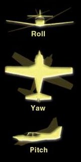
Let's say that the airplane is flying just faster than the wing stall speed, and the right wing stalls. Three things happen:
1. The airflow over the stalled right wing isn't smooth anymore, so the drag on that wing increases, effectively pulling back on that wing relative to the rest of the airplane; this causes the airplane to "yaw" to the right (the nose swings over in that direction) and enter into a spin.
2. The stalled right wing loses lift, but the left wing is still lifting. This sends the airplane into a roll as the right wing sinks.
3. Because the right wing is no longer generating lift, the total lift provided by the wings has been cut in half. The horizontal stabilizers, just like before, keep lifting the same amount as always; but because the wings are producing less lift than usual, the body of the airplane will start to sink while the tail is more "buoyant" than the rest of the airplane. This sends the airplane pitching nose-down.
At this point the airplane is in what we call "developed spin" and losing altitude fast. Recovering from this kind of spin, if this specific aircraft is able to do so (and they aren't always), requires that the pilot keep a cool head and follow prescribed spin recovery procedures.
--
Labels: engineering
Has anyone seen my brain?
... because it seems to have sprouted wings and taken off sometime in the last 30 minutes.
It can't have gotten far, right? How fast do brains fly? And what is the coefficient of lift for brain wings? What is a brain's lift-over-drag ratio? What kind of turbulent flow results from brain aerodynamics?
I can't answer these questions; I don't even know if my brain decided to wear a safety helmet.
I was doing fine up until a little while ago. I've been holed up in the lab all afternoon, so about fifteen minutes ago I took a walk upstairs to my professor's office (the one my subconscious believes is partly mechatronic) to pick up my old homework. And when I got back and sat down at my lab station, I couldn't do any more work. I think the crafty old brain took the opportunity to escape out a window upstairs when I wasn't paying attention.
I sure hope it comes back before class tomorrow.
--
Labels: engineering, everyday